Well, there are many and varied definitions of Artificial Intelligence (AI). Sci-fi has another conception of AI.
The father of Artificial Intelligence, John McCarthy, defines it as
“The science and engineering of making intelligent machines, especially intelligent computer programs”
This is how people thought about AI in its initial phase. Many Experimentation were performed, and with time layers of complexity kept on adding, and this field evolved further.
Professor Patrick Winston, who teaches at MIT, defines AI as Follows:
“it’s about algorithms enabled by constraints exposed by representations that model targeted thinking, perception, and action. ”
Alan Turing in 1950 introduced a Turing Test— A Human was made to interact with a machine, if a human wasn’t able to decide whether it is a machine or Human, then the Machine Passed the Turing Test.
Another Experiment called as Chinese Room Experiment became popular in 1960— A person was kept in a room with a huge Chinese tome, he had no knowledge of Chinese, and yet he was able to reply back in Chinese—when a letter was sent to him. He went on searching for different Chinese words in the Tome. So, even though He didn’t know the Semantics of Chinese; He was still able to respond.
In 1964 Eliza was created in MIT; It is a Natural Language Processing Computer Program.
Other topics like Fuzzy Logic, Artificial Neural Networks, and Genetic Algorithms became a part of Artificial Intelligence discourse.
But in the Contemporary times, AI is becoming much Smart; Social Networking implements it, Big Data and Data Mining goes hand in hand with it. Discussions related to Machine Learning have become all pervasive.
In near future, when Internet of Things (IoT) will be a part of our daily lives, we will realize that IoT will be Incomplete without AI , because things will be involved in decision making and AI will play a vital role in that.
Now Keeping in view these kinds of developments, and improvements in AI
Patrick Winston modifies his definition further.
“And this is an age when we begin to realize that that definition up there is actually a little incomplete, because much of our intelligence has to do not with thinking, perception, and action acting separately, but with loops that tie all those together. “
In past five decades we have come across various technological waves. At first it was the advent of Computers in our daily lives. People became overawed by the GUIs offered by Windows 98 , and then Windows XP and beyond.The Upward trend of beautifying didn’t stop. Then came Internet, although it was there for soldiers, it became popular very recently. Things like Social-media, chatting sites, all such fancy toys, made it popular. Now we are living in a time where a third wave is in its infancy. Something which was glamorised in Science-Fictions. That third wave is called as Internet of things (IoT). We can have any possible thing on Internet with this technology. And they will take part in decision making. It won’t even require Human involvement. And a part of this network contains Low-Power and constrained devices, like small miniaturised computers, with 8 bit to 16 bit processors. Merging this type of Network (Internet of things) with the Network which we are already familiar with will bring some challenges. Challenge is a mother to innovations and inventions- Border Router became the new binding force.
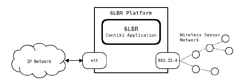
In-order to deploy IoT network, installing a Border Router (BR) is a must . Border Router is a gateway to these two different worlds , 802.15.4 (WPAN)devices are on one side of it, and Ethernet or Wi-Fi is on other side of it . One such Border router is a 6LoWPAN Borderrouter (6LBR) . See(Figure 1 ).
Figure 1 6LBR
6LBR can play a role of a Router or a Bridge. When it is a router it separates the IPv6 and 6LoWPAN networks into different Subnets (Figure 2 ).
Figure 2. 6LBR as a Router
And as a Bridge it considers both IPv6 and 6LoWPAN as a common Subnet (Figure 3).
Figure 3. 6LBR as a Bridge
6LBR can be operated as a Smart Bridge, Transparent Bridge , or a Router . Description about these modes is provided below.
Smart Bridge
In the Smart Bridge mode 6LBR allows the interconnection between IPv6 based network with the RPL based 802.15.4 Network . The Smart Bridge acts as a NDP (Neigbor Discovery Protocol) proxy on the Ethernet side and uses NDP parameters to configure the 802.15.4 Mesh.
The 6LBR provides an adaptation mechanism, here NDP configuration options are converted into RPL options. The Neighbor Discovery of IPv6 is a bit different from the Neighbor Discovery of 6LoWPAN [see.6LoWPAN]. ND proxy has been implemented to adapt 6LoWPAN-ND with NDP of IPv6. To Bridge the RPL network with the NDP network, information is collected through RPL messages,it is used for ND proxy functionalities, and the parameters received through NDP configures the RPL network (Figure 4).
Figure 4 6LBR as a Smart Bridge
Router
In this mode 6LBR behave like a Normal Router. It binds two different Networks together. The 802.15.4 Network is Managed by RPL protocol and the Ethernet side is managed by NDP. These two Networks are logically separated.Each network has a distinct prefix, for example aaaa:: for the ethernet and bbbb:: for the WPAN. Nodes are configured to route the traffic meant for WPAN through 6LBR and vice versa (Figure 5).
Figure 5 6LBR as a Router
Transparent Bridge
This mode provides basic switching capabilities. It allows multiple WPANs to be aggregated into a single RPL DODAG. Packets destined towards 802.15.4 interface or incoming packets on the Ethernet interface are forwarded to the WSN segment. Similarly , all incoming packets targeting an Ethernet interface or incoming packets on the 802.15.4 are forwarded to the Ethernet side (Figure 6).
Let me explain about the Wireless sensor Networks (WSN) part first :
These devices have the processing capability, they contain small micro-controllers ( 8bit -16 bit ), they have the sensing ability ( Temp, pressure etc) , and they have the communicating ability .
These are very small devices , they range from the size of a grain of sand all the way up to the dimension of a shoe-box.
Have small and limited power capacity .
The nodes ( sensors ) are inexpensive .
Nodes remain unattended ( You can’t go to a wild forest again once you have deployed these from a helicopter) ,they are designed for a prolonged lifetime.
The node density is high.
Networks are highly redundant .
Transmission range is small (3 to 30 meters ).
Limited resources like: Memory and processing.
Data moves from many nodes to the Gateway .
On the other hand Wireless ad hoc network (WANET) they have the following properties:
They have no sensing ability.
They are larger in size, for example :Laptops and PDA’s.
Power sources have larger capacity.
Compared to WSN they are Expensive.
Unlike WSN they don’t remain unattended. Battery can be replaced.
Node density is low .
They have less redundant networks .
Transmission range is large (10 to 500 meters).
Memory size is big, and the processing power is Higher.
Data moves from one device to many (Broadcasting )
Also called as Nano IP, 6LoWPAN is IPv6 over Low-Power Wireless Personal Area Networks. It was Developed by IETF(Internet Engineering Task Force) for Memory constrained Embedded devices. Edge Routers help a 6LoWPAN domains to get into the internet. Edge Router performs Three main tasks :
Exchange of Info between 6LoWPAN devices and the Internet.
Data exchange between the devices Present in 6LoWPAN domain.
Generation and maintenance of the radio subnet (6LoWPAN Island)
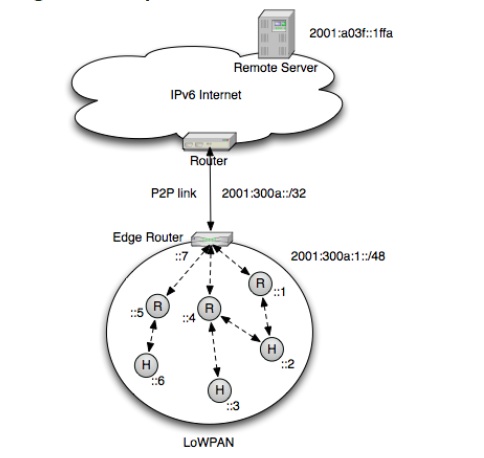
Figure 1 All devices inside same 6LoWPAN domain share the same prefix [1]All the motes or devices within a 6LoWPAN domain share the same Prefix (IPv6 addressing ) [see Figure 1]. Two other important devices that are enabled in 6LoWPAN networks are : routers, and hosts. Figure 1 Routers (R), and Hosts (H). Routers route the packets to another device in the 6LoWPAN domain, and Hosts On the other hand are not capable of routing data, they go into there sleeping cycle a, and as they wake-up , they look for their parents.
Bringing the Low- power and constrained devices on IPv6 was quite challenging initially, However , IPv6 over Low-Power WPAN (6LoWPAN) group was established to enable IPv6 over IEEE 802.15.4 . The 6LoWPAN protocol is primarily focused on applying IPv6 over MAC and PHY layer of IEEE 802.15.4 .
It faced two key challenges [2]:
The maximum fame size allowed by IEEE 802.15.4 is only 127 bytes, and a part of it will be for the header, hence the available payload size is limited.
The Minimum value of Maximum Transmission Unit (MTU) for IPv6 is 1280 bytes.Since the MTU supported by lower Layers is smaller, therefore data link layer should fragment and reassemble the data packets.
To address the above challenges , an adaptation layer was designed . This 6LoWPAN adaptation layer is just above the data-link layer. It segments the IPv6 packets into small pieces for the lower layer. Figure 2 shows the 6LoWPAN protocol stack. The 6LoWPAN adaptation layer is shown as a separate layer, but during Implementation IPv6 and 6LoWPAN ; together are considered as a single layer (Figure 3).
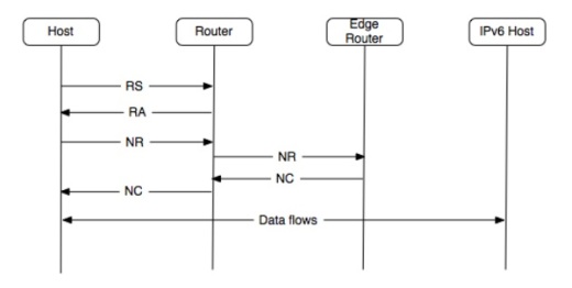
One of the key features of IPv6 is the Neighbour Discovery (ND). It assumes that all devices are on all the time. It is like everyone is shouting at every other device to get connected. But in 6LoWPAN such Neighbour Discovery is not appropriate , as we have sleepy devices, some even wake up after weeks. Here the device that wants to get connected registers itself with the router, so instead of everybody shouting at everybody we have a wireless device shouting at the router and registering it self. Figure 4 shows the ND .
Figure 4 6LoWPAN Neighbour Discovery [1]Here we have four Message types :
Router Solicitation (RS)
Router Advertisement (RA)
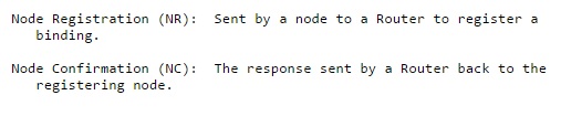
Node Registration (NR)
Node Confirmation (NC)
RS and RA are common to both 6LoWPAN and IPv6 Neighbour Discovery (ND).
Router Solicitation (RS) originate from hosts only, these messages are send to detect the presence of Routers on the link. Routers respond to these messages by sending RA.
Router Advertisement (RA) messages originate from routers ,these messages indicate the presence of router on a link. These messages contain essential parameters along with IPv6 prefix of the network. All routers send out these messages periodically to allow the hosts to participate in 6LoWPAN network [3].
Below is a brief definition of Node Registration (NR) and Node Confirmation (NC) taken from the IETF website, to know more in detail follow the link [6LoWPAN ].
Mobility in 6LoWPAN:
Mobility involves the Movement of Nodes , it involves two processes :
Roaming: It is the movement of a node from one network to another. Handover: Here the point of attachment changes.
There are three types of mobility :
Micro-mobility : It involves the movement of a node within the same IP Domain or WiFi infrastructure, the IPv6 prefix stays the same. Macro -Mobility : When a node moves from one IP domain to another. Here the IP address changes.
Figure 5 shows Micro-Mobility and Macro-Mobility .Both fall under the category of Node Mobility.
Figure 5 Node-Mobility [1]
Network Mobility : Here an entire 6LoWPAN moves, the point of attachment of the edge router changes. One can think of it as a Network of nodes present In a truck, and as the truck moves, its point of attachment also keeps on changing. Figure 6 shows Network-Mobility.
Figure 6 Network Mobility [1]
How to confirm that Motes are using 6LoWPAN in Network Layer
Just follow these steps :
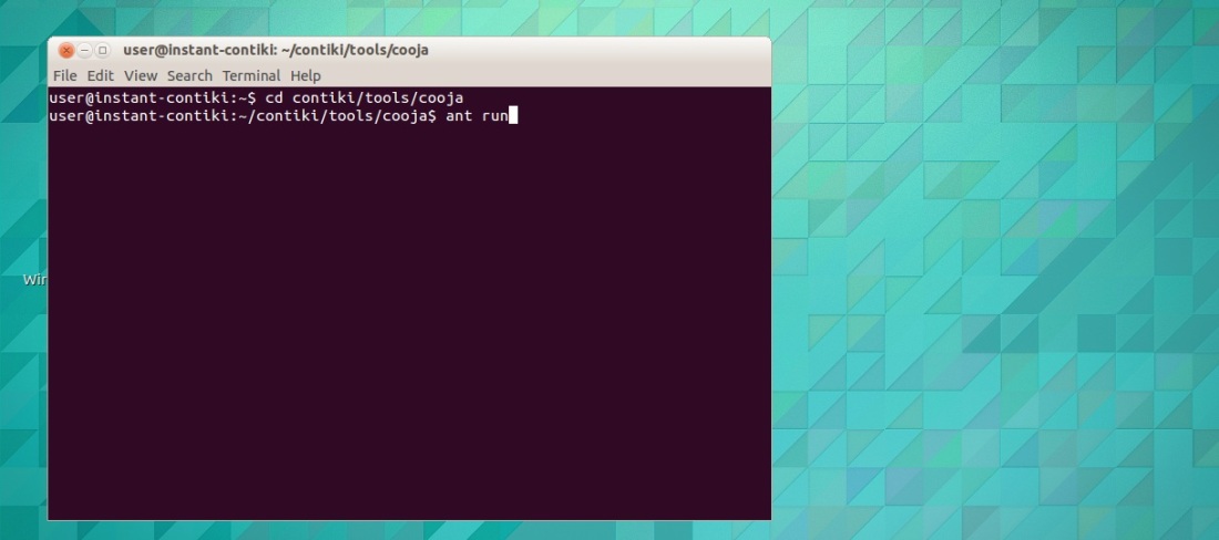
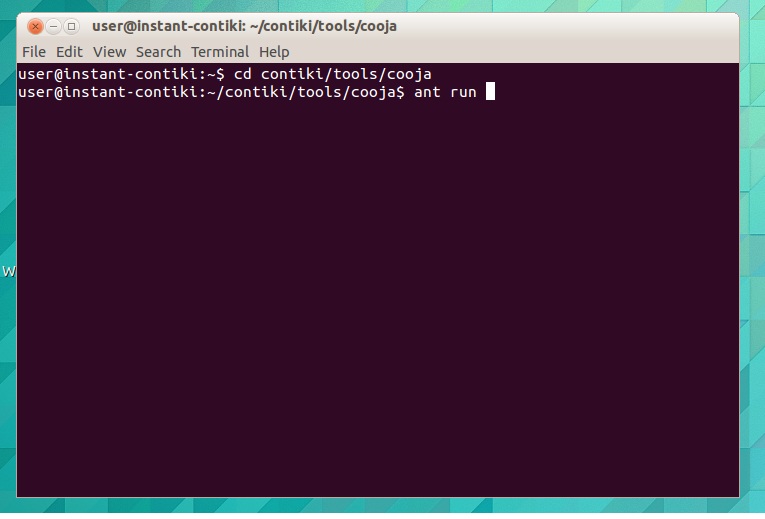
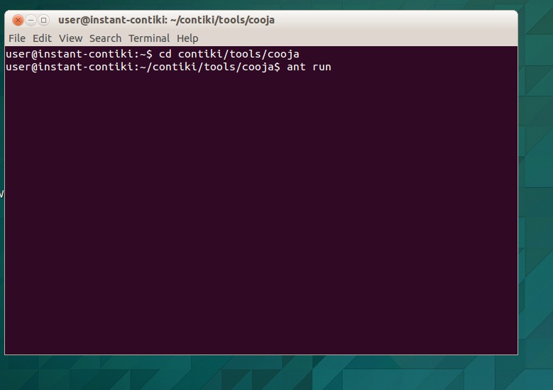
You need to have Contiki OS and the Cooja simulator . Once you boot your system go to the Terminal , and press type the following command:
cd /contiki/tools/cooja
ant run
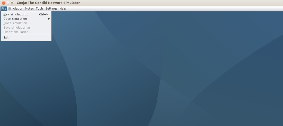
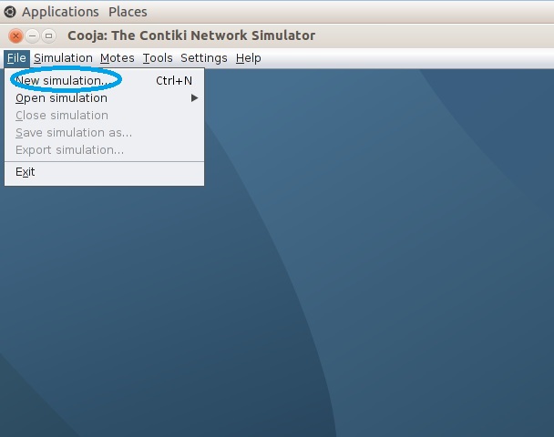
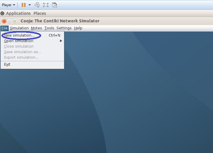
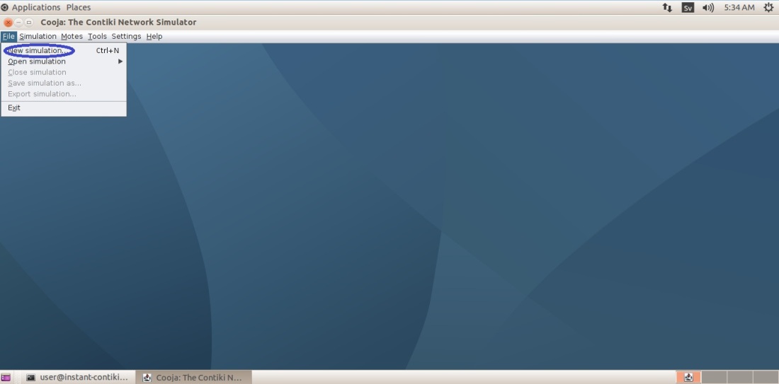
Now wait for the Cooja Environment to pop up. Click on the New Simulation
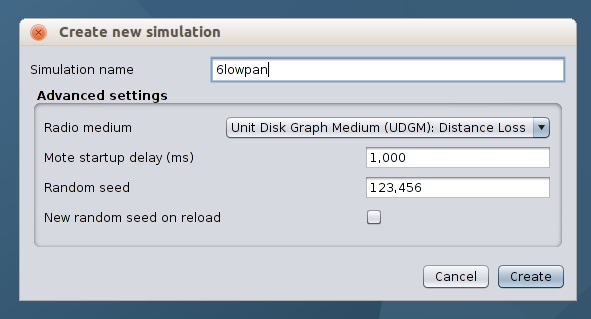
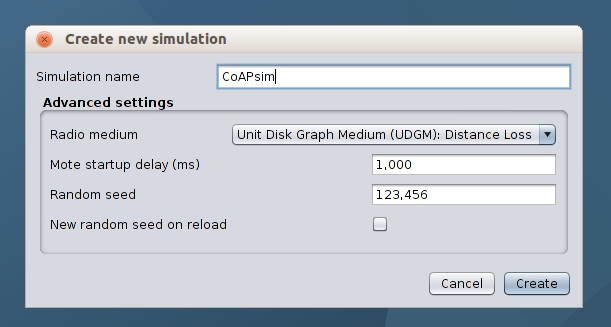
Give it any name .
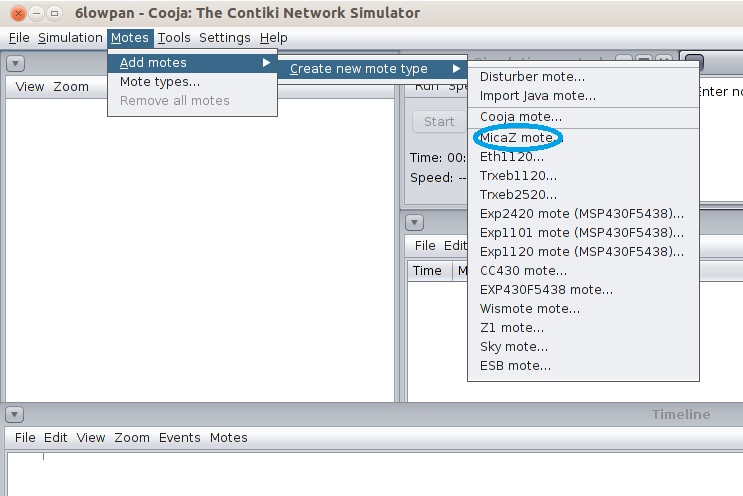
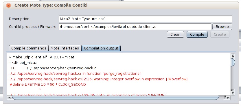
Let us Begin with MicaZ mote. Go to Motes-> Add Motes -> Create new mote type-> MicaZ mote
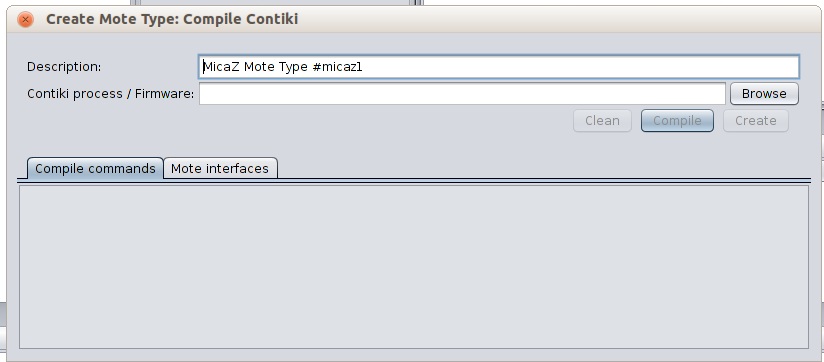
Click on Browse
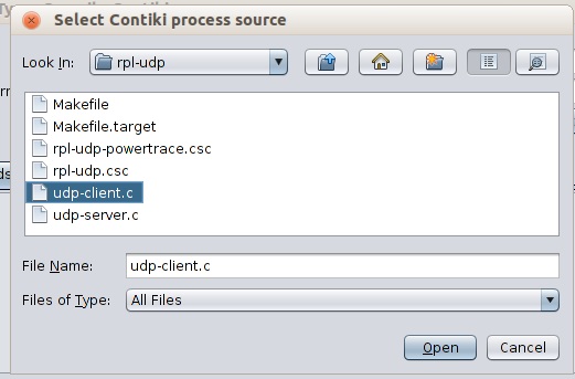
Go to examples/IPv6/rpl-udp/udp-client.c
If we press compile, it will show an error therefore we won’t be able to create it. The error occurs because MicaZ motes don’t support 6LoWPAN application.
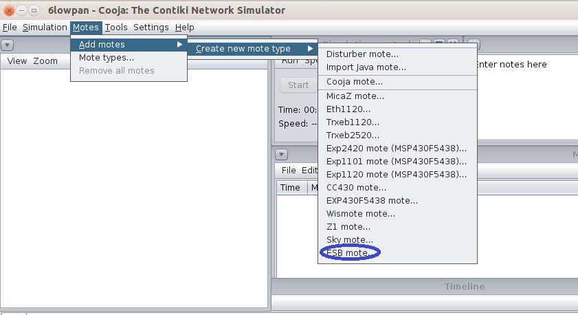
Close the window ,and let us choose ESB motes
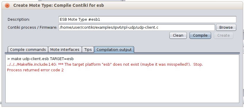
We choose the udp-client as in Step 6.
And press compile. We will get an error in ESB mote Just like we got in MicaZ mote. These errors occur because they don’t have need of IP Support.
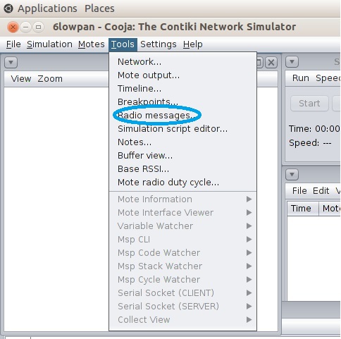
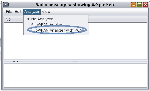
Close the Window. Now we will try Sky Motes. Before that we need a packet analyzer Display, that will show the 6LowpAN packet traffic. For that Click on Tools-> Radio messages.
Radio Messages window will pop-up. Click on Analyzer->6LoWPAN Analyzer with PCAP
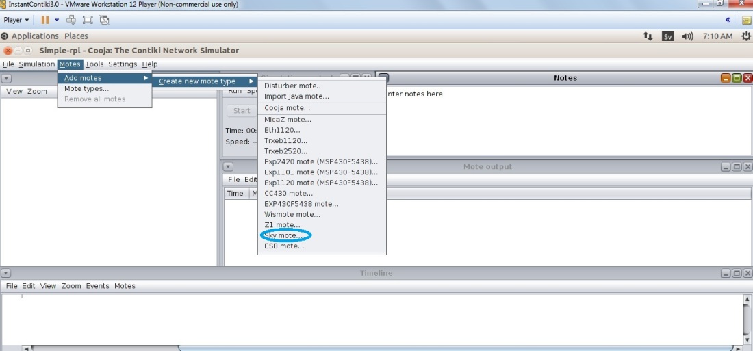
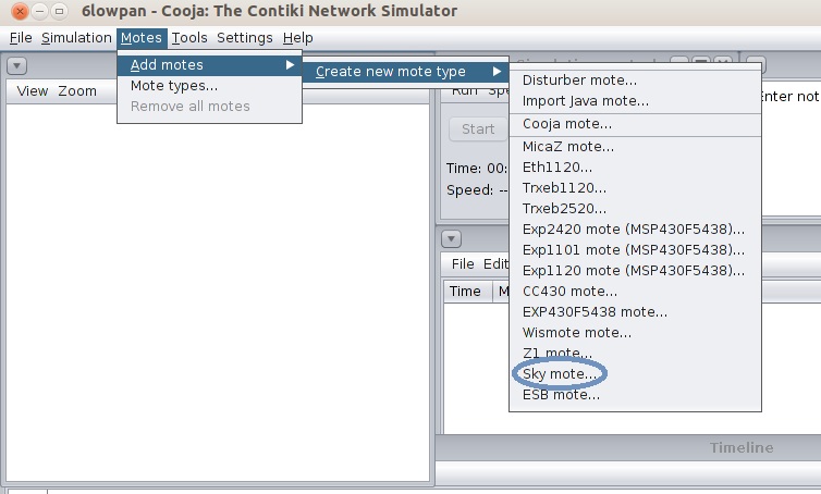
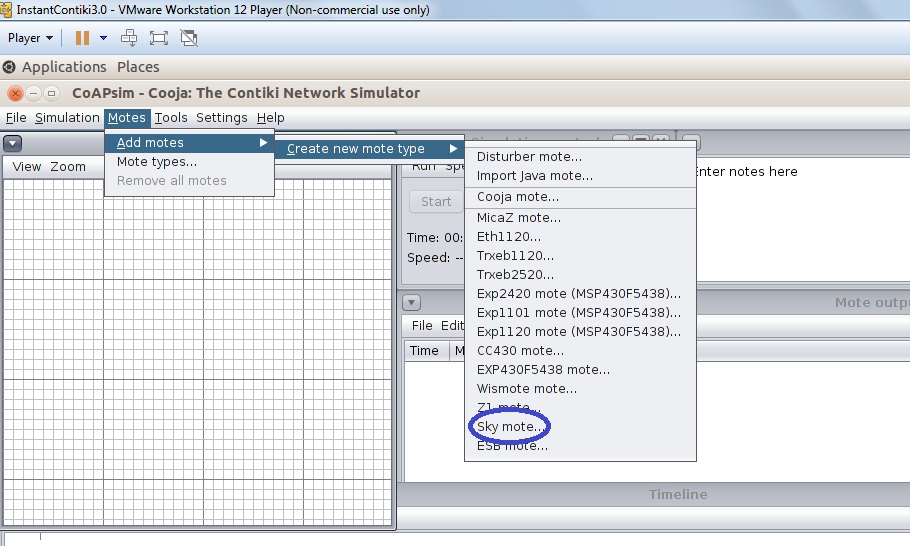
Go to Motes->Add Motes->Create new mote type->Sky mote
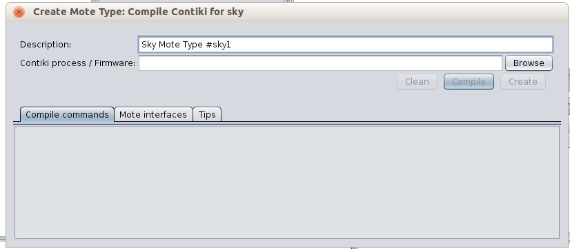
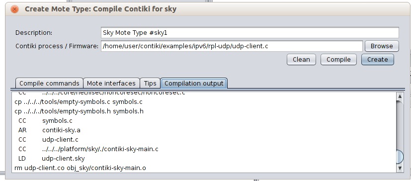
As the Create Mote type Window appears, press on browse and locate udp-client.c as in step 6 and step 9.
Press compile , you will be able to compile it smoothly . And press create
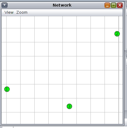
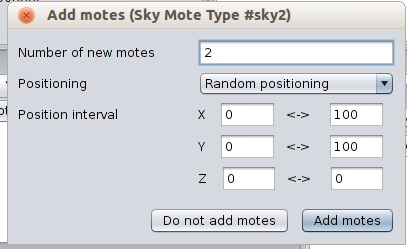
Select as many motes as you want.
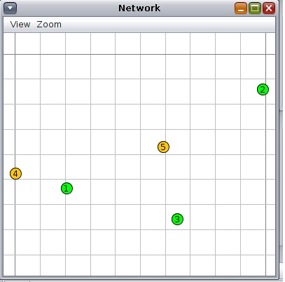
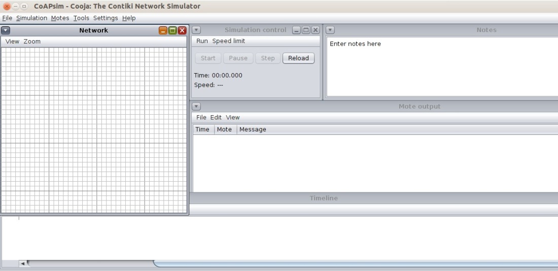
Network Window will pop up.
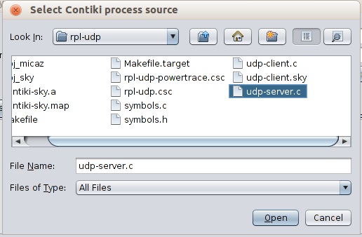
Again choose the Sky motes like in step 13
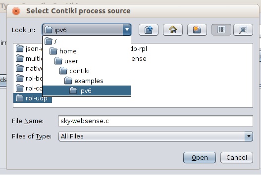
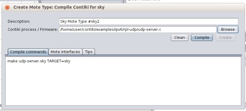
Following window Will appear Click on browse and locate examples/IPv6/rpl-udp/udp-server.c
Press compile . wait for the Completion ,and press create.
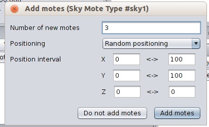
Select the number you want.
22. Following window will appear.
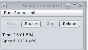
23. Press the Start Button in Simulation Control Window.
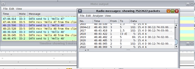
24. And the Radio message Window displays the traffic. It clearly means that our network Supports 6LoWPAN in its Network Layer.
25. They overall environment might look like the following screen-shot.
Congratulations !!!!
You can check the Video of Output in the below given link :
Small devices are unable to communicate with constrained resources. In addition to that Internet of things (IOT) has to take care of heterogeneity. As billions of different sensors, computers , and other communication elements need to be connected together, which may work on different protocols. Therefore, to tackle this problem Internet Engineering Task Force (IETF) has developed Constrained Application Protocol (CoAP). It is one of the largest application protocols meant for Smart dust.
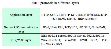
Wireless protocols mainly fall under three layers : PHY/MAC, Network/Communication, and Application layer (Table 1).
Source [1] IOT uses TCP & UDP protocols. UDP is less complex when compared with TCP . This makes UDP a good choice , but the only problem is that it is not stable, to take care of that it needs to be combined with Application layer. Since HTTP is also an application layer Protocol, one can think of using it , but its problem is computation complexity, low data rate and high energy consumption. Therefore it won’t suit for constrained devices. IETF came with numerous protocols like Embedded binary HTTP (EBHTTP ), Lean Transport Protocol (LTP) , and CoAP.
With the completion of CoAP millions of devices will be in Application Domain : Smart Grid, Smart Homes, Smart Environments. Constrained RESTful Environments (CORE) is the group that designed CoAP.
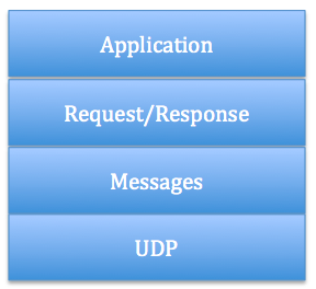
CoAP is not a replacement for HTTP, but is is a new design, which comes with features to accommodate the limitations of HTTP. CoAP employs a two layer structure (figure 1 ). These two layers are : Message Layer, Request/Response layer . Message Layer supports four types of messages: CON (Confirmable) , NON (non-confirmable), ACK (Acknowledgement ) , and RST (reset) [for more details refer Constrained Application Protocol for Internet of Things]. Message layer is meant for Re-transmitting lost packets. Request/Response layer contains methods like GET, PUT, POST and DELETE.
Figure 1 : Two layer structure of CoAP
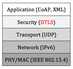
As discussed CoAP is an application layer Protocol, and it needs security. Therefore, to get the authencity, integrity and confidentiality, it implements Datagram Transport Layer Security (DTLS) in Security layer (Figure 2) . DTLS deals with packet loss and does the reordering .
Figure 2 : DTLS in protocol Stack
CoAP is similar to HTTP Client/Server Model. HTTP is based on REST ( Representational State Transfer ). and is based on “The Web ” architecture. Resources are the key to web. Servers contain original state of resources. Clients access these resources with the help of GET, PUT, POST and DELETE methods. CoAP works with CoAP directly, but to work with HTTP it uses Proxy ( intermediary enabled by the REST architecture) [see Figure 3] . Proxy behaves like a Server to a Client and then a Client to a Server. Just like a URI scheme for HTTP ,COAP also has a URI scheme which is written as coap:// .
Figure 3 : HTTP and CoAP working together [2] Cooja Simulation of CoAP :
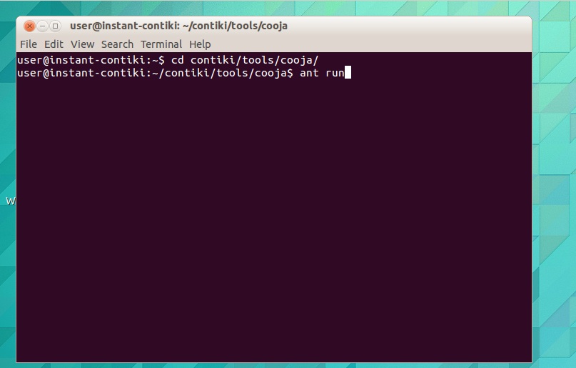
To run CoAP simulation in Cooja we nee to take the following steps :
After logging into your Contiki OS , go to the terminal and type the following .
cd /contiki/tools/cooja
ant run
Wait for the Cooja screen to open , go to File–> New Simulation . Then give any name to your to your simulation once the Create new simulation window appears.
To display the Grid, radio traffic , ID etc, refer my previous blogs .
Go to Add motes–> Create new mote type –> Sky mote
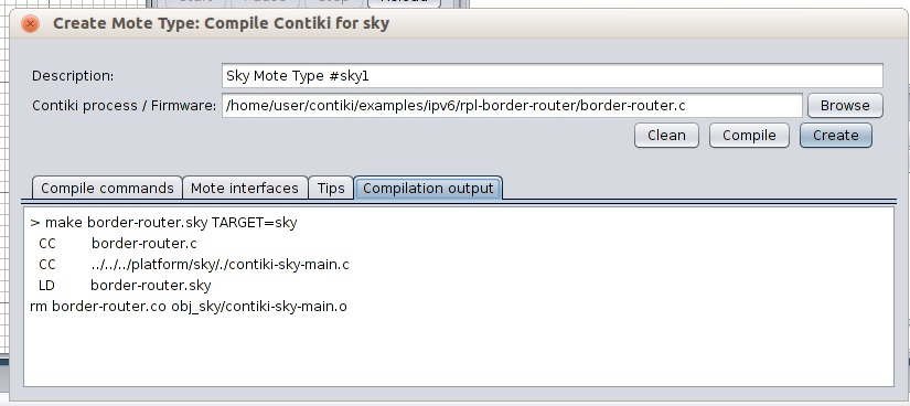
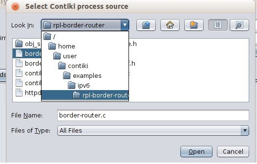
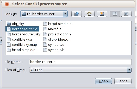
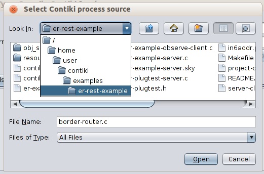
Once the Create Mote type window appears click on browse and locate examples/ipv6/rpl-border-router/border-router.c
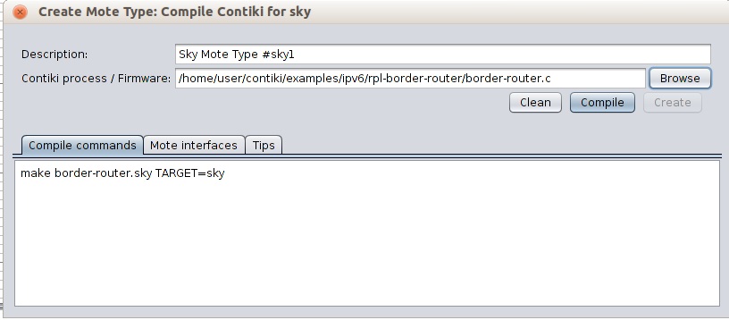
Press Compile, wait for some time , and press Create
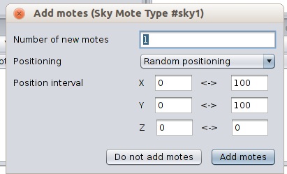
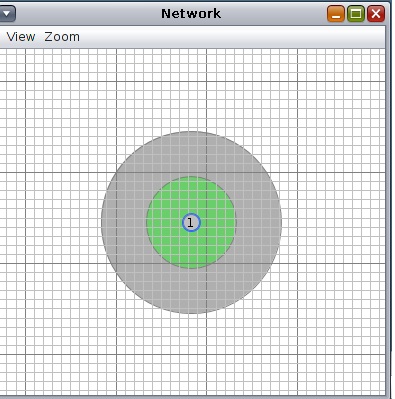
Select one mote .
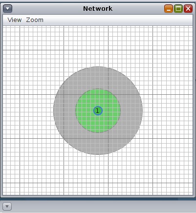
To see the radio coverage ( green Area) , click on the mote . if it doesn’t show up go to view–> Radio Environment.
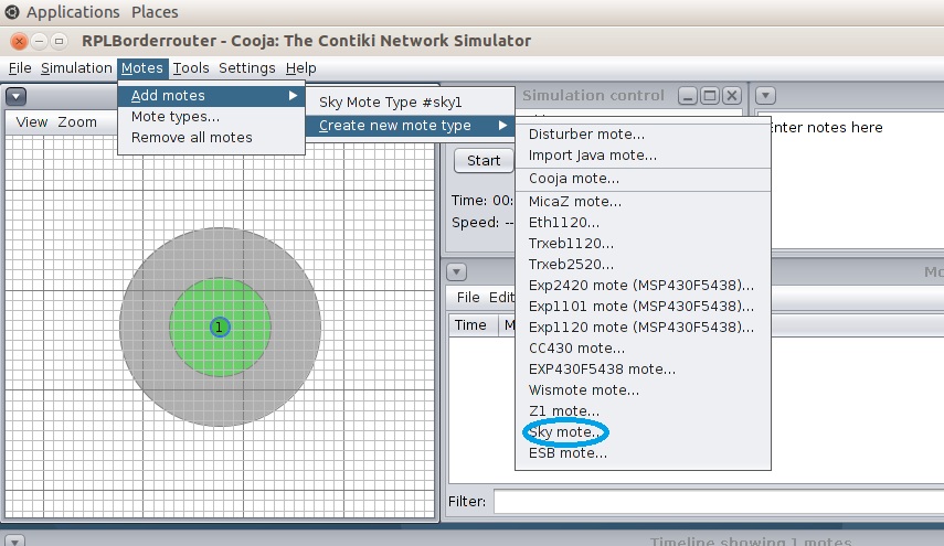
9. Repeat step 4, go to Add motes–> Create new mote type –> Sky mote
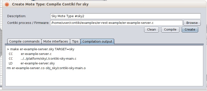
10. Locate examples/er-rest-example/er-example-server.c . Press Compile , wait for some time , and Press create
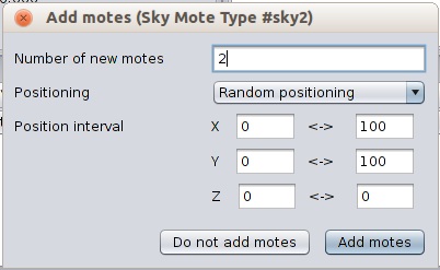
11. Select the number of motes you want
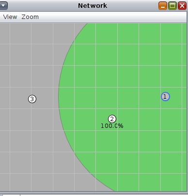
12. Let us keep mote 2 in the range on mote 1 , and mote 3 in the range of mote 2.
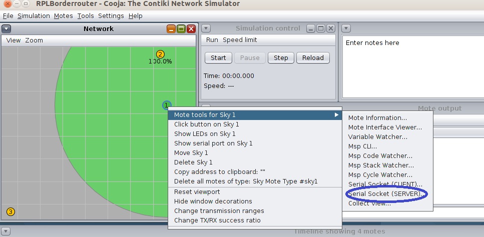
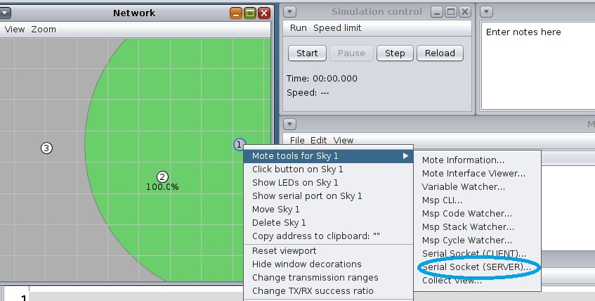
13. Before connecting the Border router , right click on the Mote 1 (Border Router ). Go to Mote tools forSky 1—-> Serial Socket (Server).
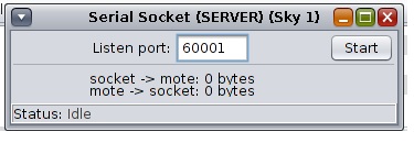
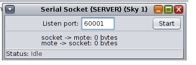
Serial Socket server window will appear, press start.
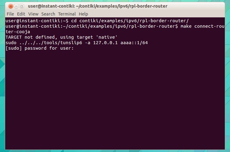
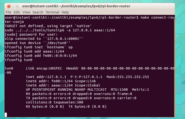
14. Before running the simulations , we need to connect the border router. Open a new terminal and type the following:
cd contiki/examples/ipv6/rpl-border-router/
make connect-router-cooja
Type the password as user
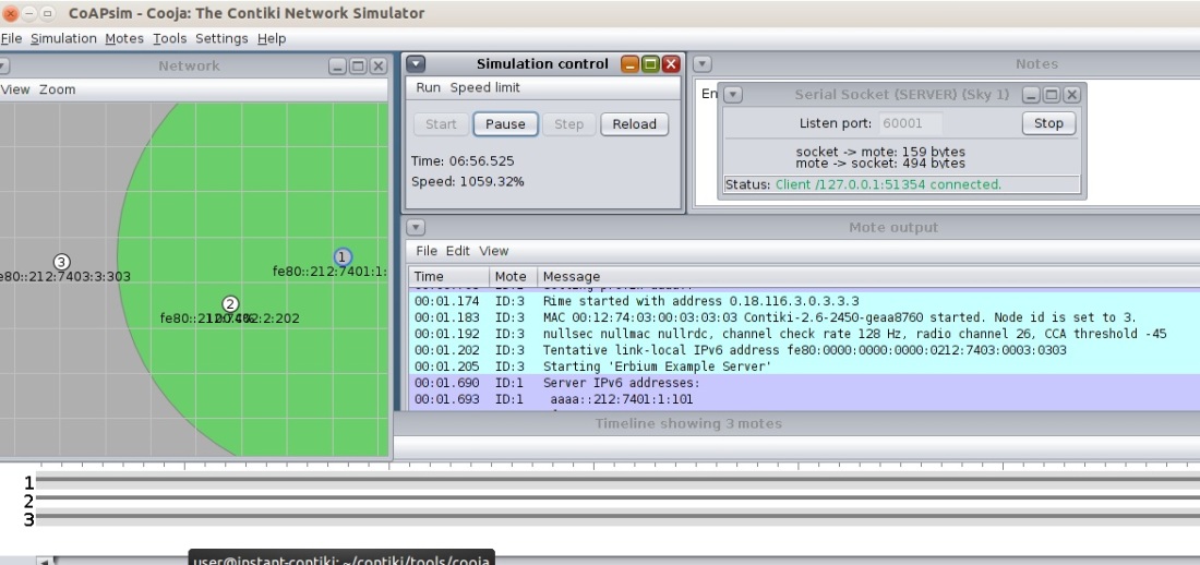
15. Go to the simulation control Window and press start, you will see the radio traffic flowing in the Network Window.
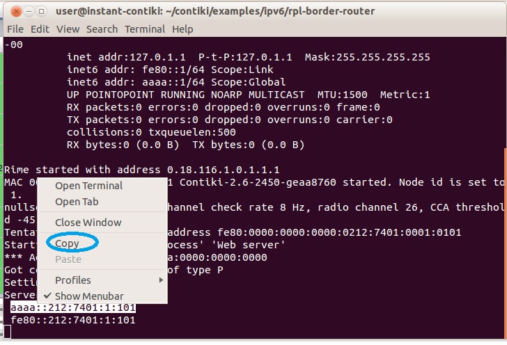
16. Go to Terminal widow and copy the IP Address of the Border Router
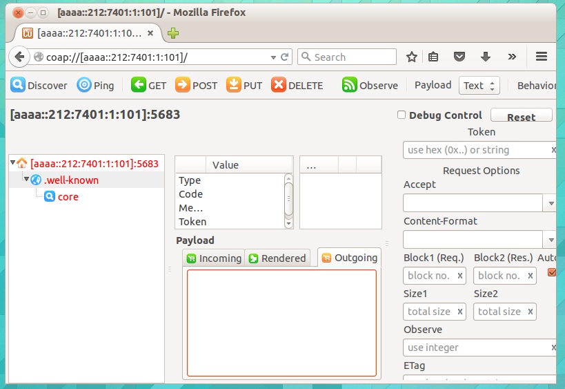
17. Now go to the Internet Browser and paste this Address with the coap://scheme
you can also type IDs of other nodes , and as we know that GET ,PUT, POST are the methods used by the client to access the resources from Server.
As the name suggests , Border Router can be found at the Edge or Border of a Network. They bridge one network with another. RPL Border Router is used to connect a regular IP network with a RPL 6LoWPan network.
One can also think of it as a Gateway that brings two different networks together. And a typical example is that of IEEE 802.15.4 on the Wireless Sensor Network(WSN) side and Ethernet or WiFi on another Side. Figure 1 Shows a Border Router.
Figure 1 Border Router Connecting RPL network with Rest Of the Internet
To know more about RPL Protocol, please check my previous Blog, link is provided below:
While doing the Cooja simulations. We need to focus on two main things:
Border-Router : Which helps to get on the Internet.
Web-Server : It allows the Border Router to connect to the Internet.
The Cooja Simulation for a Border Router is Performed through the Following Steps:
Go to terminal and type the following :
cd /contiki/tools/cooja
ant run
And wait for the Cooja Window to show-up
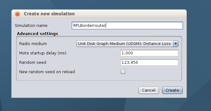
Click on New Simulation
Put any Simualtion name and press Create
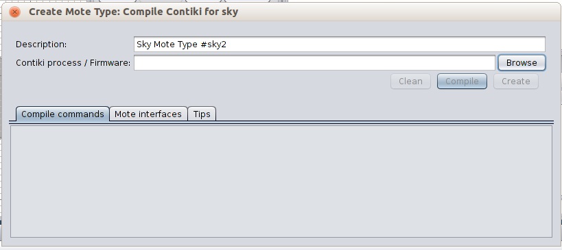
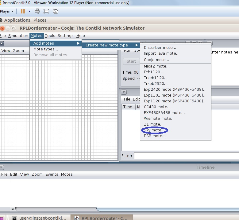
Go to Motes -> Add motes ->Create new mote type ->sky mote
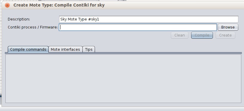
A new window will appear.
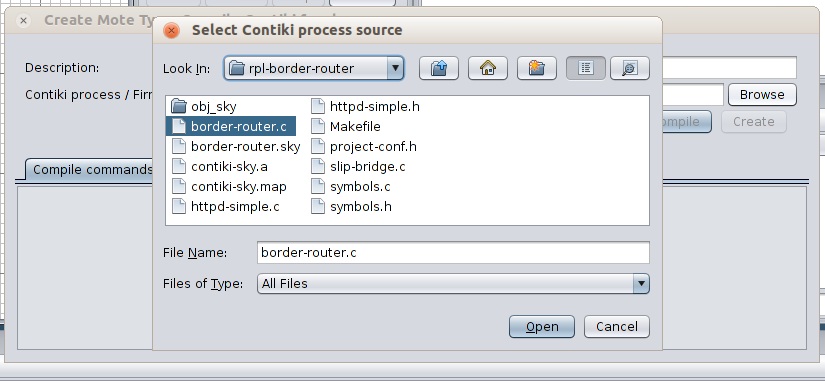
Click on Browse and Locate ipv6/rpl-borderrouter/border-router.c
Press Open.
You will return back to the Create Mote Type window. Press compile, wait for some time, press create.
Select 1 mote. Press the Add Motes tab.
Following appears on the Network Window.
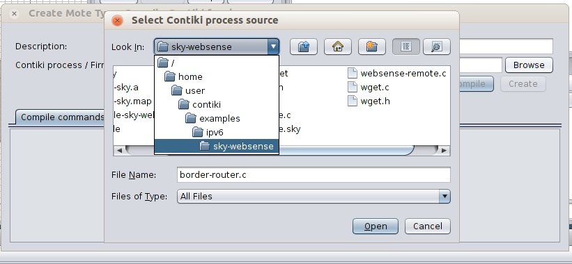
Go to Motes ->Add motes ->Create new mote type ->sky mote
A New window shown below Will Appear . Click on the Browse.
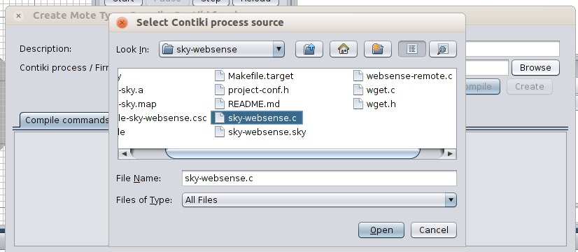
Locate examples/ipv6/sky-wensense
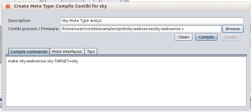
And select sky-websense.c . And Press open
Press Compile, wait for Some time and Press Create.
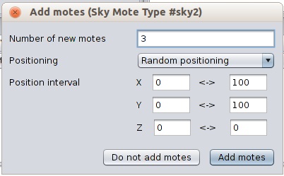
Select as many Motes as you want from the Add Motes window.
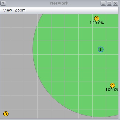
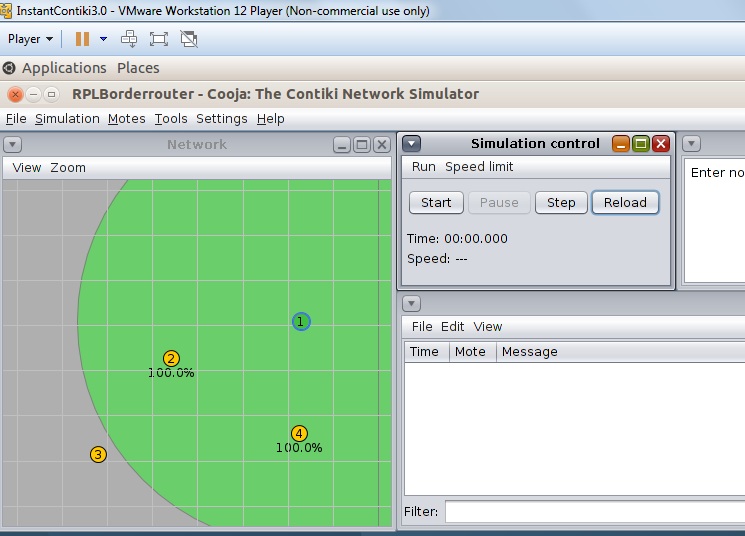
13. Below Network Window show the random dispersion of these motes .
Press right Click on Border Router and select Mote tools for Sky 1 ->Serial Socket (Server)
The Serial Socket (SERVER) window will appear. Press Start .
Open a new terminal window and type the following .
cd contiki/examples/ipv6/rpl-border-router/
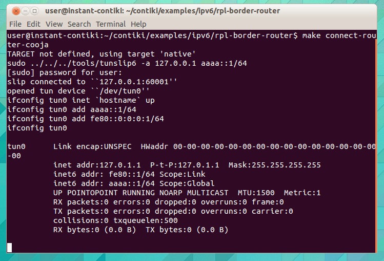
make connect-router-cooja
It will ask for password. Press User . And yield the Following Results. Tun is a protocol, which is used for capturing packets.
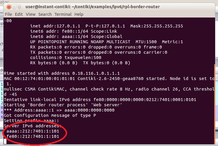
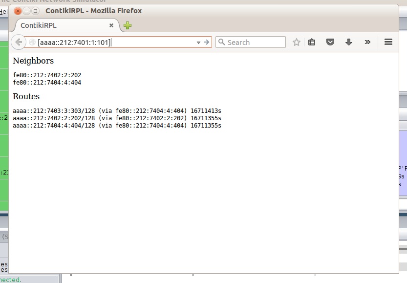
Now go back to cooja , and press start on the Simulation Control Window. Now go back to the Terminal. It will display the IPv6 address of the Border router as highlighted in the below scree-shot.
To confirm about the working of the border Router just copy the IP address and past it in Mozilla Firefox web browser. If it works correctly , it will display the Border -Router Neighbours and the routes.
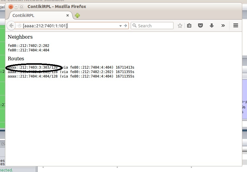
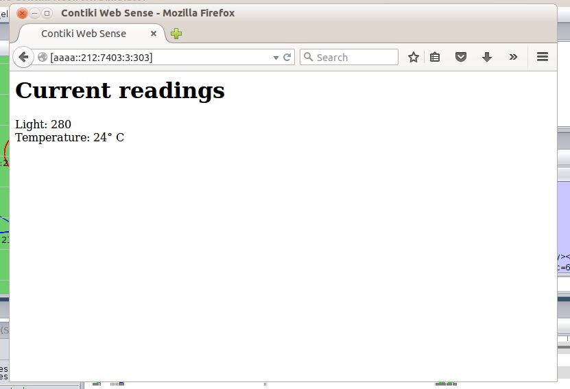
Since each Mote has a purpose, we a check whether they are Measuring the Light and Temperature properly. You can check them one by one, by entering the IP addressees of these motes in firefox. Just copy any of the address displayed in the above Route and , then paste it in firefox address blank, and see the results.
Something like the Below screen will be displayed, which shows that the Mote is working correctly.
Routing Protocol for Low power and Lossy Networks (RPL) is a distance vector routing protocol, here the routing is based on Destination oriented Acyclic graphs or DODAGs.
Before Understanding RPL and How these DODAGs are formed, we need to understand some basic terminology, and Key concepts , which are at the Heart of this Routing Protocol.
Directed Acyclic Graph :
It is a Graph that contains no cycle (Figure 1), we see such kind of graphs in Spanning trees.
Figure 1 (DAG)
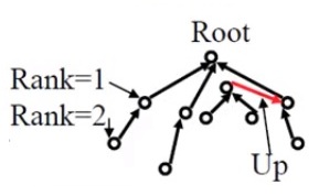
Root : it is the destination of the nodes in DAG, it has no outgoing edge.
Up : It is any edge that is directed towards the Root (Figure 2).
Down : It is any edge which is directed away from root.
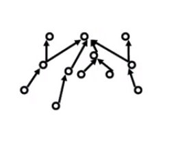
Destination Oriented DAG (DODAG) : This a special kind of DAG where each node wants to reach a single destination (Figure 2).
Figure 2 DODAG
Objective Function : It helps us to decide whether we are near to the root or away from it. Objective Function is decided by a programmer or designer . It is something which we want to minimize. It can be energy, it can be Latency. And once we decide what we want to minimize, we give it a Number.
Rank : As shown in Figure 2 , it is the distance from Root.
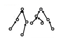
RPL instance: When we have one or More DODAGs, then each DODAG is an instance. Figure 3 shows two RPL instances.
Figure 3 Two RPL Instances
DODAG ID : Each DODAG has an IPv6 ID (128 bit). This ID is given to its root only. And as long as the root doesn’t change ID also doesn’t change.
DODAG Version: Each new shape Of a DODAG means a new version.
GOAL: It is where a DODAG wants to reach, it can be a Wired network. Goal is different that Objective function. In objective function our aim is to minimize. However Goal is where we want to go.
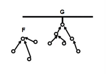
Grounded : When a DODAG reaches its goal it is known as Grounded. G in Figure 4 shows Grounded DODAG.
Floating: When a DODAG isn’t connected, or is yet to reach the Goal, it is called Floating. F in Figure 4 Shows Floating DODAG.
Figure 4 Floating and Grounded DODAGs
Parent: Parent is where the Arrow is pointing towards. And a Child is where the arrow comes from. Parents can have multiple children, Similarly a child can have Multiple parents.
Sub-DODAG : It is any subtree of a given DODAG.
Storing : Storing nodes keep the whole routing table. They know how to go from one node to another.
Non-Storing : They are simple, they don’t store an entire Routing Table, they only know about their Parents.
The whole DODAG except from the root has to maintain a uniformity, it has to be either Storing or Non-Storing. Root is always Storing.
RPL Control -messages:
There are 5 Control Messages, they form the Spanning tree :
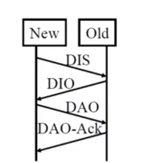
DODAG information Object (DIO) : This message is Multicasted downwards . A given node In a DODAG may multicast this message , which lets other nodes know about it , Things like whether the node is grounded or not, whether it storing or non-storing, and it announces other nodes “if they are interested to join , Please Let Me know. “
DODAG Information Solicitation (DIS) : When no announcement is heard, and if a node wants to join a DODAG it sends a control message , For that it wants to know If any DODAG exists. So the message which it sends is Like “ Is there any DODAG ? “
DODAG advertisement Object (DAO) : It is A request send by a Child to parent or root. This message requests to allow the child to join to a DODAG.
DAO-ACK : It is a response Send by a root or parent to the child , this response can either be a Yes or No.
Consistency check : deals with security , and We need not to know much about it now.
Figure 5 shows various Control messages
Figure 5 Control Messages
DODAG formation :
Root In a DODAG is a special node. All nodes don’t have the capability to be roots. A root is programmed that way.
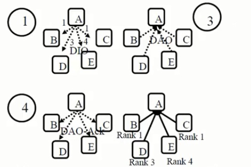
Suppose We have 5 nodes : A, B, C, D and E. And they to make a DODAG, then following steps are taken:
A multicasts DIOs .
Rest of the nodes ( B,C,D and E) upon receiving DIOs will try to join regardless of their distances. Upon receiving the DIOs they also come to know that their Distance from the A are 1,1,3,4 Respectively.
Then B, C, D and E send DAOs to A.
A accepts them by replying with DAO -ACK.
Figure 6 shows the above steps.
Figure 6 DODAG formation
Figure 6 DODAG formation
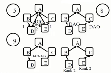
Now another round begins, and it starts with the Nodes that are nearest to the root. Since B & C have a rank of 1. They start sending DIOs.
D receives those and figures out that its distance from B & C is 1 & 2 Respectively .
Similarly E receives these DIOs , and it figures out its distance from B & C to be equal to 2 & 1 respectively .
Since D is closer to B and E is closer to C, therefore , D Sends DAO to B and E sends DAO to C.
To finalize the DODAG formation , B sends a DAO-Ack to D , and C sends a DAO-Ack to E.
See Figure 7.
Figure DODAG formation
If you have no idea about cooja and contiki , kindly check my previous Blogs , links are shown below.
If you want to do a Cooja Simulation of RPL, then the steps gives are as under :
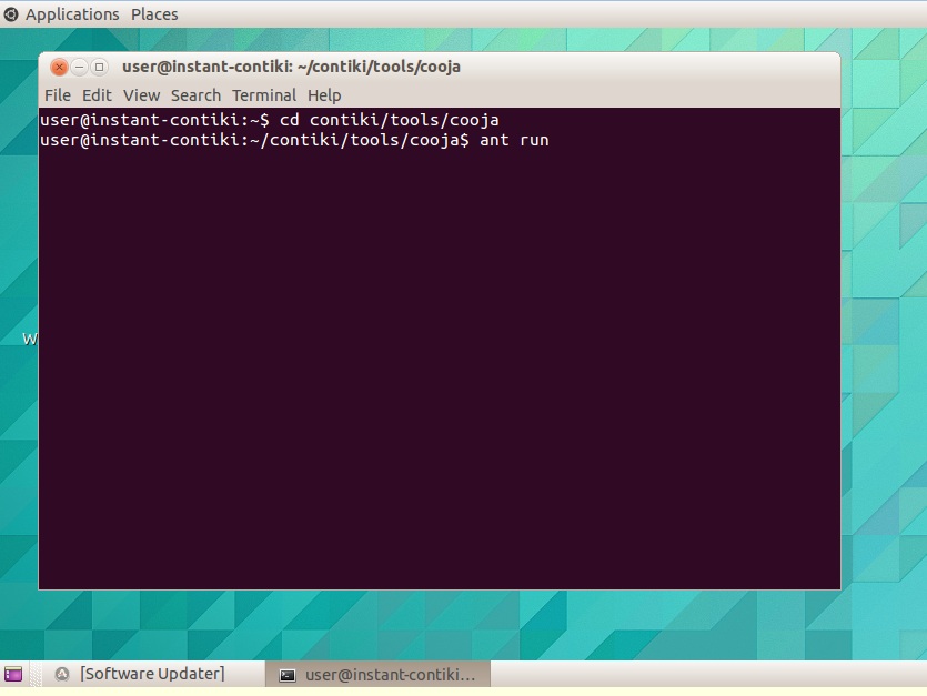
Go to the terminal and Type .
cd contiki/tools/cooja
ant run
Wait for the Blue screen of Cooja.
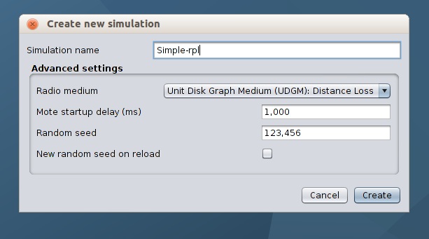
Go to File menu, select New Simulation, and save it as Simple-rpl.
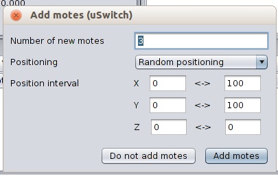
In current Simulation we will use Uhubs and USwitches. Uhub is the central entity, while as USwitches are the devices that are connected to the Uhub, for controlling light etc.
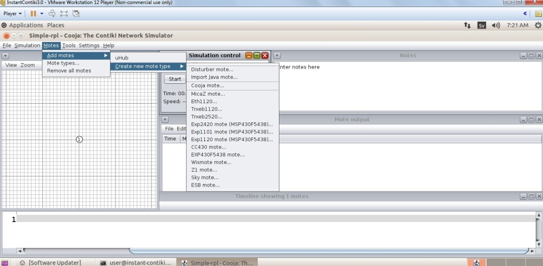
To have this Centralized System (Uhub) we have to click on Motes menu, select Add Motes, then choose Create new mote type, and finally press on the Sky Mote button.
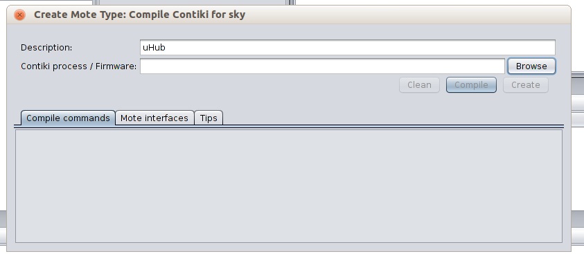
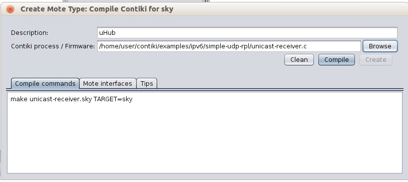
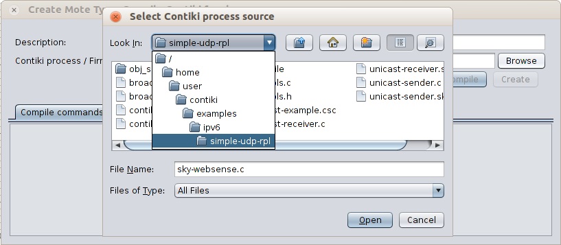
Create Mote type Window will appear. Type Uhub in the description and click on Browse.
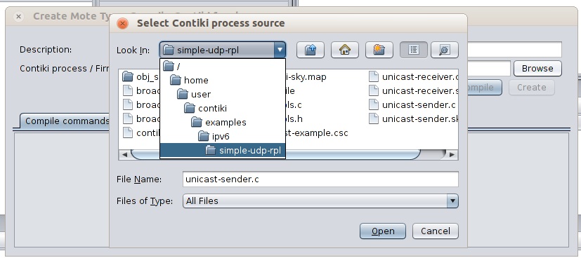
Locate simple-udp-rpl folder as shown below. /examples/ipv6/simple-udp-rpl
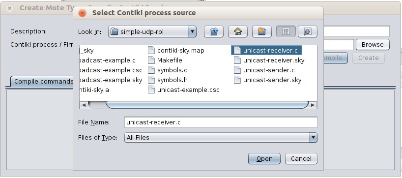
From this folder Select unicast-receiver.c
You will return back to the window which appeared in Step 5. Click on Compile, wait for Some time and finally press Create.
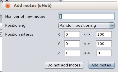
Select One Mote.
1st mote shows up on the Network window.
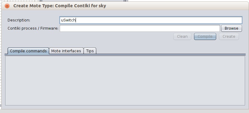
Now again for Choosing Uswitches, follow the same steps as in Step 4. Add Motes ->Create new Mote Type ->Sky mote.
New window Will appear , type Uswitches. And Click on Browse.
Locate Simple-Udp-rpl as in Step 6 and Select unicast-sender.c
In Add motes window add as many motes as you wish .
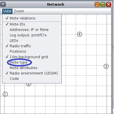
To differentiate between motes, go to view and select mote types.
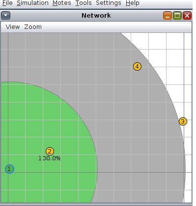
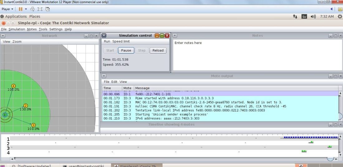
Below Figure shows the random arrangement of these motes, the green are shows the Radio range of Uhub.
one can keep all the Uswitches Within the radio range of Uhub , by dragging them one by one as shown below.
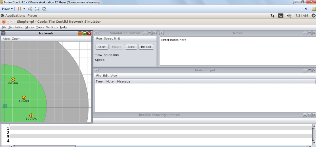
After Pressing the Start button in Simulation Control window, one can see the Traffic between these motes.
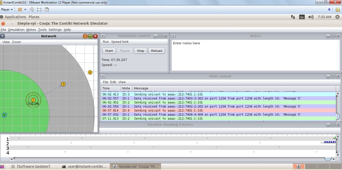
One can even Move them out of the Radio range of 1, e.g. we can keep 2 in the range of 1, then 3 in the range of 2 , and finally 3 in the radio range of 2. As shown below.
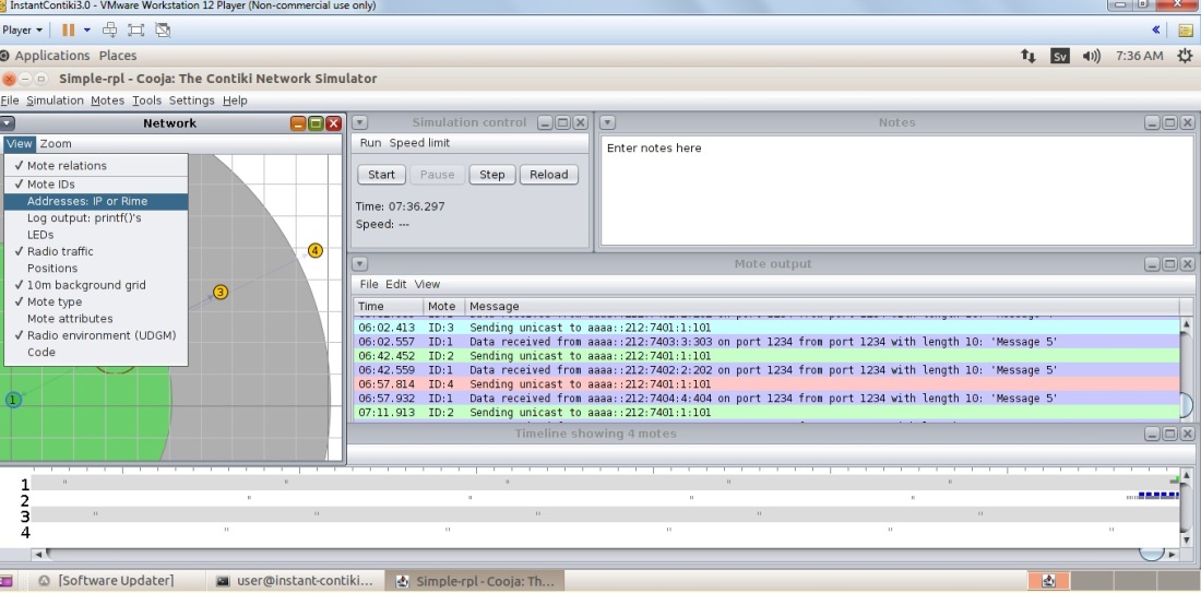
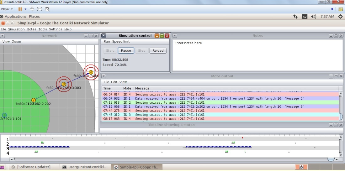
To identify various Motes by their IDs, we can go to View -> Address IP or Rime .
Here 4 makes the use of 3, 3 makes the use of 2, and finally 2 makes the use of 1.
This Finishes our RPL Simulation in Cooja. Congratulations.
Cooja is a Java-based Simulator provided by Contiki. It is able to perform simulations of different levels from Physical to Application layer, and unlike other simulators it is capable of emulating motes e.g Tmote Sky (see Tmote Sky below). As an emulator Cooja enables your Laptop to behave like a mote.
It is a handy tool for Contiki as it allows developers to test their codes and systems before running it on the target hardware.
Tmote Sky:
It is a Low power Wireless sensor, contains integrated humidity, temperature, and light sensors. And it is capable of having inter operability with many IEEE 802.15.4 devices. To know more about Tmote Sky ,follow the links given below :
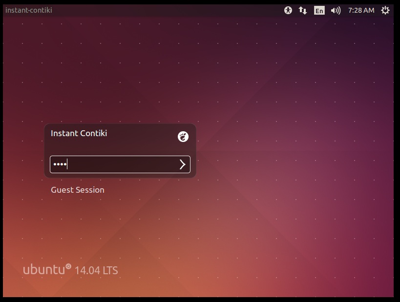
1. Boot the Ubuntu , and press user as the password (this is a default password).
2. Now go to terminal and type the following
cd contiki/tools/cooja
ant run
3. Wait for Cooja window to appear. Once it appears click on file menu , and go for New Simulation.
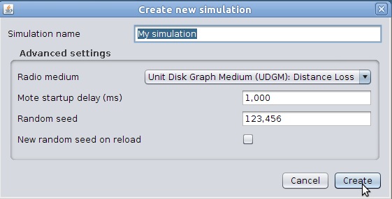
4. Above step opens Create New Simulation, here the Simulation shows My Simulation, just go with it and press Create.
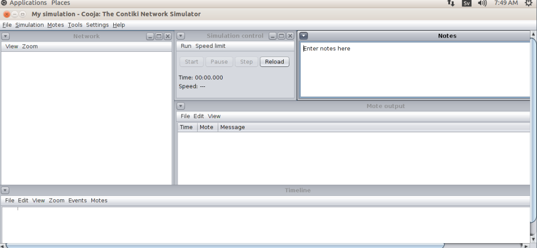
5. It will cause numerous windows to Open. Table 1 shows the function of these windows.
Table 1 Function of Various Windows
6. If Network Window is without Grids then go to view menu and click on 10m background grid.
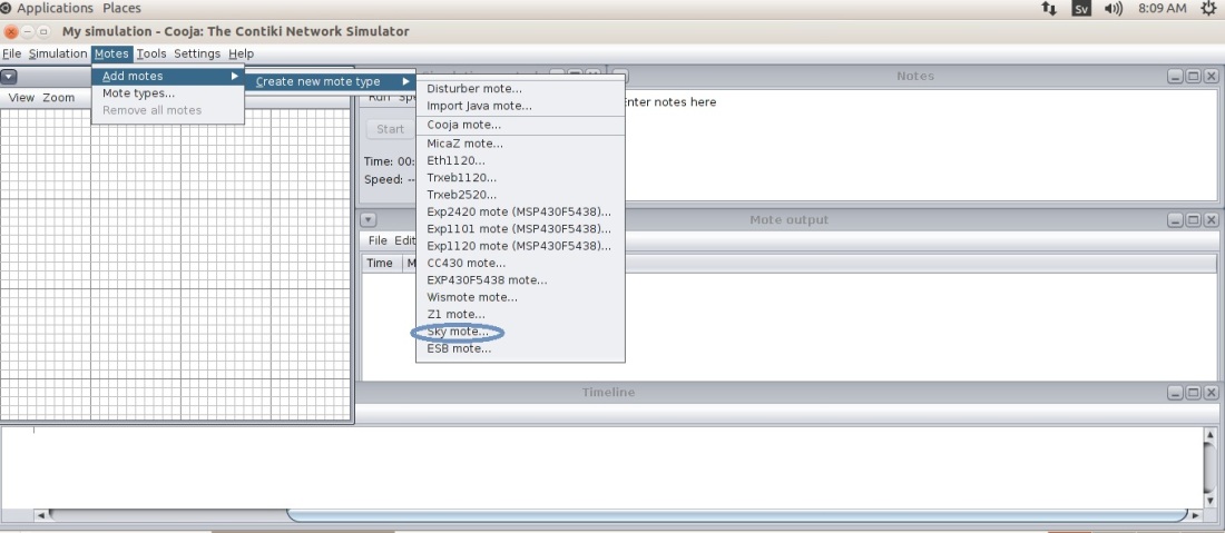
7. Now Go to the Motes menu, choose Add motes, click on Create new mote type , and finally choose the Sky mote option. we choose Sky Mote option to emulate Tmote Sky motes.
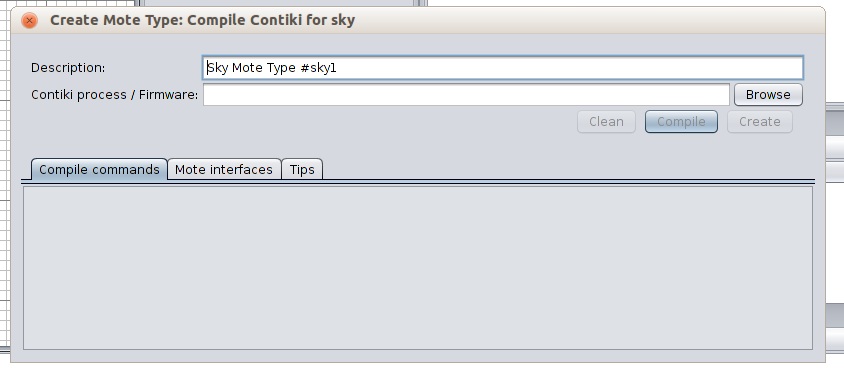
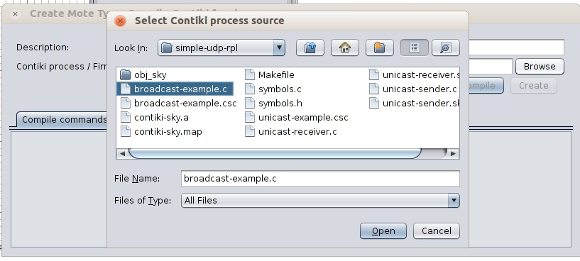
10. Now choose the file broadcast-example.c and press Open.
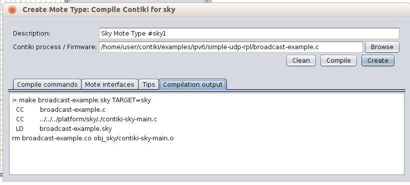
11. You will return to the Menu obtained in Step 8, press compile, wait for some time, and finally press Create.
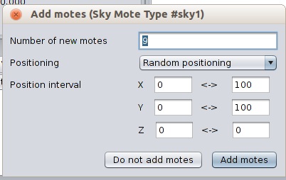
12. Add motes Window will appear, Select as many as you wish, and press Add motes.
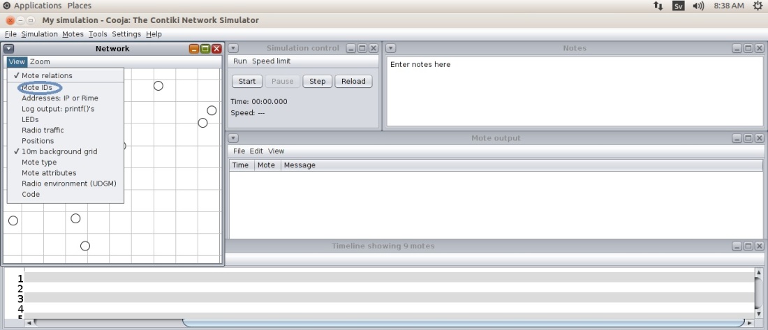
13. To differentiate between these motes, go to View Menu in Network Window and press Mote IDs.
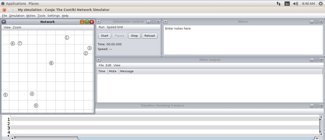
It will provide a number for each mote.
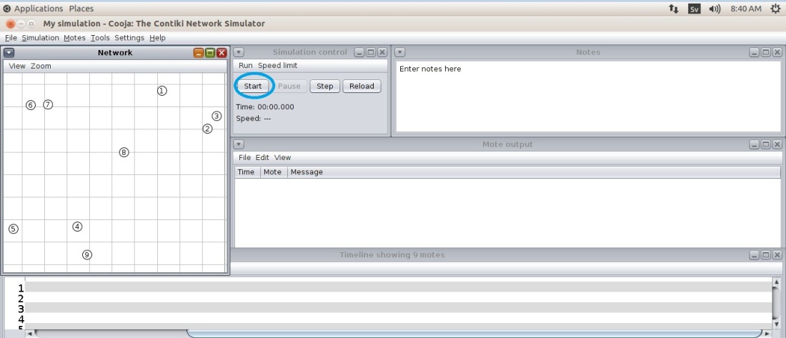
14. To Monitor the Radio Traffic select Radio traffic from the View Menu. And Press Start button to begin the Simulation.
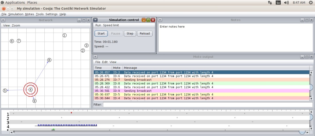
15. Press the Pause Button, You will get to see the Communication in the Network Window, there will be printout of the simulated motes in the Mote output window. And this Marks the end of Our Simulation.
Contiki is just like any other popular Operating System, but it was designed for some specific purpose. Contiki OS is an Open Source meant for Internet of Things (IOT) , and is expected to bridge trillions of tiny low-cost, low-power microcontrollers , including tiny Wireless Sensors (Smart Dust) on the Internet.
Apart from being highly portable , and multi-tasking Operating System it has some other interesting features like the Communication Components. These Communication Components include uIP and 6LoWPAN.
uIP otherwise known as “micro IP” , was designed to incorporate minimal set of Components , that are necessary for a full TCP/IP stack. It was meant for tiny 8 and 16 Bit microcontrollers, and this stack includes TCP, UDP, and ICMP protocols (Figure 1) . The size of uIP code is few Kilobytes, and RAM requirement is just few hundred bytes.
Figure 1 Components of uIP stack
uIPv6 is the worlds smallest certified IPv6 stack, and is a part of Contiki. It was initially developed by CISCO, was meant for sensors and actuators , and is used for thousands of projects all over the world.
On the other hand 6LoWPAN is a framing mechanism that enables the use of IPv6 over the MAC and PHY layer of IEEE 802.15.4, and makes IPv6 packets run over these Radio Links effectively .
IPv6 is a new addressing protocol. It is the successor of IPv4. Although IPv4 Is a promising protocol, But the number of devices on the Internet are proliferating at an unprecedented rate. In near future we will run out of addresses, and in that case people will be forced to share from the 4 billion addresses (2^32 addresses) . Therefore, to avoid this saturation, there is a need of a special protocol which can be implemented in Future version Of Internet (also called as Version 2), and IPv6 became a good choice.
Internet Engineering Task Force (IETF) formalised IPv6 by 1998. Unlike the 32 bit long addresses in IPv4, these IPv6 addresses are 128 bits long , and offer an address space of 2^128, which is almost equal to 340 trillion trillion trillion addresses. Figure 1 provides an Idea. Some of the Internet Giants Like Google choose to Implement IPv6 on June 06, 2012.
Figure 1 One can estimate this huge range
IPv6 is not backward compatible with IPv4, these are two different protocols. Therefore, it is impossible to switch the entire internet over to IPv6 Overnight. Hence, the pragmatic approach is to make these two versions work side by side. And this may last long (Even a decade) , and for that a transition mechanism is needed to bridge between IPv4 and IPv6.
Two popular technologies that enable the transition are:
Dual Stack
Tunneling
Dual stack : In this technique Nodes with IP stack will contain both IPv4 and IPv6. Figure 2 shows the stack.
Figure 2 Dual stack
While communicating with IPv6 node, IPv6 part is used and when communicating with IPv4 node, It Uses IPv4. Figure 3 Provides an Idea.
Figure 3 Dual IPv6/IPv4 Stack
Tunneling: This technique is implemented when Different IP versions exist on Intermediate path. Suppose two IPv6 nodes want to communicate via IPv4 routers. Then IPv6 packets are placed inside Ipv4 packets as shown in Figure 4.
Figure 4 Tunneling Mechanism with IPv4 as intermediate node
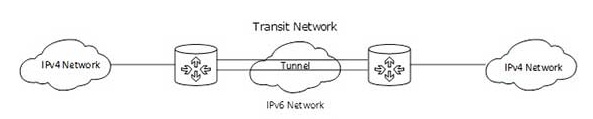
Similarly, reverse can happen, where the transit network is IPv6 (Figure 5).
Figure 5 Tunneling Mechanism with IPv6 as intermediate Node


 Press Open.